
Mercedes-Benz performance intake systems (intake kit) can replace or reorganise several factory inlet-side parts together, so pipe routing, filter-side hardware and heat shielding need to work as one package. The right starting point is clean fitment and a stable air path.
The correct version depends on Mercedes-Benz platform, year, engine code, sensor layout and free space in the engine bay. Use filters, then confirm the vehicle list and joining details on the product card.
Verify exact dimensions and specifications on the product card; in-stock items dispatch fast within the EU. Before installation, do a dry test-fit so the pipe, shield and clamps are not loaded against bodywork or sensor connectors.
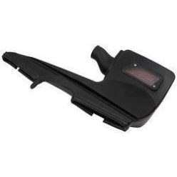
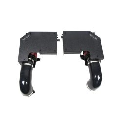
Net price: 427 €
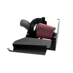
Net price: 244 €
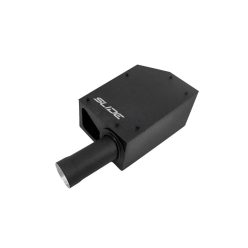
Net price: 262 €
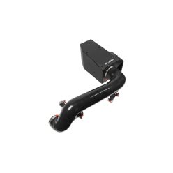
Net price: 345 €
Mercedes-Benz Performance Intake Systems & Airboxes: Fitment, Air Path and Heat Control
Mercedes platform logic: These full Mercedes-Benz inlet-side kits (performance intake assembly) deal with several factory intake elements together, so pipe routing, filter position, heat shielding and sensor connections matter just as much as the filter itself. The system stays more settled when there is room for engine movement, thermal expansion and even sealing contact at each join.
Current focus: The present Mercedes-Benz range on this page is centred mainly on W176, C117 and X117, X156, W205, W213, GLC, plus M276 and M264-based fitments, so exact platform and engine-code checking matters from the start.
Technical background and system integration
Air path: On Mercedes-Benz platforms, pipe radius, filter location and sensor housing design work together to influence how settled the airflow remains before the measuring point. That is why exact engine code and sensor layout matter at least as much as engine size.
Heat control: In turbocharged Mercedes-Benz engine bays, it is especially important to see where the kit draws fresh air from, how well the filter is separated from the hot side, and whether there is enough clearance around the pipe when the engine moves under load.
- Routing: The cleanest installation is the one that does not preload the pipe against the headlamp area, fan shroud or strut tower.
- Sensor position: Check that the MAF or MAP connection, as well as any auxiliary take-off, sits on the correct side and angle.
- Airbox logic: With a closed design, the lid fit, sealing edges and fresh-air feed need to work as one system.
How to choose the right one?
Quick selection guide: Start with Mercedes-Benz model, platform and engine code, then use the product card to confirm the exact vehicle list, sensor compatibility and whether the kit uses an open filter layout or a more closed airbox configuration.
Platform split: W176, CLA-based C117 and X117, GLA-based X156, plus W205 and W213 applications can differ in pipe routing, sensor position and space claim, so the same engine family alone is not enough for a safe choice.
If you are comparing multiple Mercedes-Benz fitments, lock in platform and engine code first, then check the joining layout and filter-side arrangement on the product card.
Installation and failure-prevention tips
Surface preparation: Couplers and joining stubs should be clean, burr-free and dry. Degrease using a manufacturer-recommended cleaner, then allow to dry completely before applying load/boost. This matters most on silicone or rubber joins where even sealing contact helps the system settle properly.
Seating: Tighten clamps progressively while checking that the pipe is fully seated around the full circumference, the heat shield is not acting as a stop, and there is still enough clearance when the engine moves under load.
Common failure: On Mercedes-Benz intake systems, unstable idle, a changed intake note or a fault code often appears when the pipe is slightly twisted on the join, the sensor housing orientation is wrong, or an auxiliary take-off is not fully sealed; clean seating, a dry test-fit and an inspection after the first heat cycle usually prevent that chain of issues.
PRO TIP: After the first road test, recheck clamp position, free space around the filter and whether the pipe has started touching any nearby part that could slowly wear the surface during vibration.
FAQ
What should be my first check order if fitment does not look clean after installation?
Start with sensor housing direction, auxiliary take-off sealing, clamp position and whether the pipe is fully seated. Then confirm that nothing has been pulled out of line around the headlamp area, fan shroud or strut-tower area.
How does a full intake system differ from a panel filter?
A panel filter usually stays inside the factory airbox, while a full intake system changes the pipe route, filter location and often the heat-management strategy as well. That gives more freedom over the whole inlet path, but it also makes fitment details more important.
What should I inspect if I get an engine light after installation?
Check sensor plugs, vacuum or auxiliary hoses and each joint next to the clamps first. Then make sure the pipe or filter is not interfering with the loom, and confirm that the sensor housing size matches the specification shown on the product card.
Is an open filter or a closed airbox better for my car?
If the engine bay is tight and exposed to more hot-side radiant heat, a closed layout may offer a tidier thermal strategy. An open system can still work well when the fresh-air feed and shielding are properly managed.
When should the system be inspected and cleaned?
For road use, it is sensible to review filter condition, clamp seating and the surrounding pipe area at regular intervals. Dusty, wet or harder-used cars usually benefit from more frequent checks so movement or contamination is spotted earlier.
