
Our Master Kill Switches & Pull Cables range covers fast, reliable power isolation: 2/4-pole kill switches, interior/exterior pull cables, panels, looms and mandatory stickers. Choose proper current rating, add an alternator dump resistor, and use vibration-proof mounting to ensure consistent shutdown on road and track.
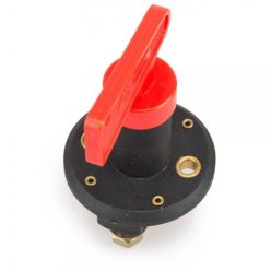
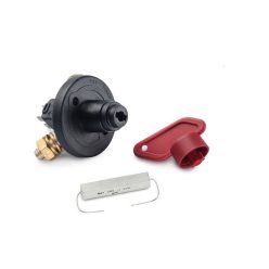
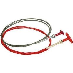
Net price: 14 €

Net price: 14 €
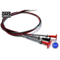
Net price: 14 €
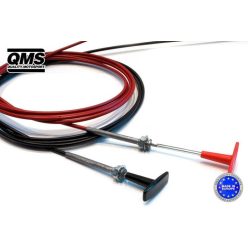
Net price: 19 €

Net price: 24 €
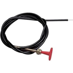
Net price: 31 €
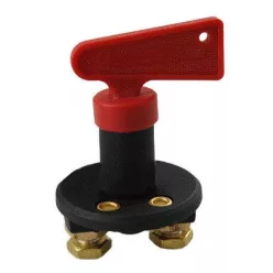
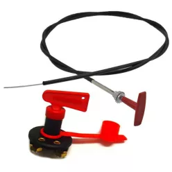
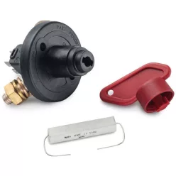

Net price: 2 €
Brief summary & key benefits
Master Kill Switches & Pull Cables enable rapid isolation of the vehicle’s electrical system. The right current rating, adequate cable gauge and a clearly marked external pull meet safety and scrutineering demands. Modern switches add alternator protection via a dump resistor and arc-resistant contacts for durability under vibration and high cranking loads.
Technical Basics
Two designs dominate: 2-pole units interrupt the battery positive; 4-pole units also drop the ignition/ECU feed or shunt the alternator field to a resistive load. Always check DC continuous and peak ratings—underspec’d contacts overheat and wear prematurely. A low-friction pull cable (bowden) allows interior/exterior actuation; generous bend radii and rigid mounting reduce effort. Mounting panels and hardware create a vibration-proof installation, and standard stickers indicate the exterior handle location.
Marking requirements typically call for a red lightning or “E” symbol near the exterior handle. Use weather-proof labels and a contrasting handle; place it where marshals can reach it quickly (A-pillar base or grille area).
Selection Criteria
Rating: size above expected continuous load and verify cranking capacity. Prefer manufacturers that specify DC ratings and cycle life.
Poles: for alternator-equipped vehicles choose 4-pole switches with a proper dump resistor/diode path; simple builds with separate ECU relays may use 2-pole units.
Wiring: short runs, large mm² conductors, crimped lugs, proper fusing near the source and clean, low-resistance grounds.
Pull cable routing: smooth, heat-free paths with large radii; secure the sheath at bulkheads and add a weather cap externally.
Mounting: rigid panels, multiple fasteners and edge protection; orient the lever so the OFF direction is unambiguous with gloves.
Installation & Maintenance
Isolate the system before work. Mount the switch within driver reach and route the pull cable with gentle bends; lightly lubricate the inner wire. Implement the manufacturer-specified dump resistor/diode for alternators. Perform static and running tests after installation; re-torque terminals after initial heat/vibration cycles. Periodically inspect loom abrasion points, sticker condition and cable smoothness.
Common pitfalls include undersized switches, long thin power runs, tight or kinked bowdens, missing exterior markings and omitted alternator protection—each can cause slow actuation, excess heat or ECU damage.
FAQ
Q: 2-pole or 4-pole—what should I use?
A: Choose 4-pole for alternator cars (includes protection); 2-pole can work on simple setups with separate ECU feeds.
Q: Where should the exterior handle be?
A: A visible, quickly accessible location—commonly the A-pillar base. Add the required sticker and a weather cap.
Q: What cable size do I need?
A: Size by peak cranking current and length; high-current paths demand large mm² and short runs.
Q: Why fit a dump resistor?
A: It absorbs alternator-induced spikes at cut-off, protecting the ECU and charging system components.
Q: How do I maintain the pull cable?
A: Periodic cleaning, light lubrication and verifying large bend radii; replace damaged sheaths immediately.
